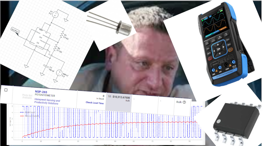
Ive been in a creative/motivational null with developing my game so I wanted to do some hardware things to get my mind off of it. About two years ago I had this idea that I wanted to make a bunch of very small modular synths for myself/friends. So I spent around 3-4 months accruing passive components, a crappy amazon box of misc active components (Similar to but not exactly this one), a breadboard that I never got rid of from college and a few Arudino boards lying around. The last 3-4 months I wanted to grab an oscilloscope off of facebook marketplace (there’s some older HP’s on there that seemed neat) but instead of commuting hard to $150 I instead spent $60 ish on this guy and started re-learning everything that I spent hundreds of thousands of dollars to learn in college (as my day job has been mostly software for 3+ years).
THE PLAN
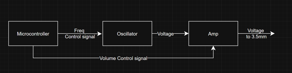
So my goal is to make a simple oscillator for playing audio frequencies, which I’ll claim is 0.01hz to 2000hz. With a frequency that is controlled by microcontroller.
You might ask me “hey why don’t you just use the microcontroller as the oscillator? You can literally attach a capacitor to the pwm and use it as a pseudo dac” . Good point, I have three counter points:
- Then I would claim its a digital synthesizer not an analog one
- Way Less Cool
- Shut up
———-
Now that I have the plan in order I can take stock to see what I even have:
- Bunch of passive components (Inductors, resistors, capacitors)
- 555 timers (NE555)
- Misc op amps (LM358, LM324, NE5532, JRC4558)
- Voltage comparitors (LM339, LM393)
- Nand gates (74Hc00)
- Class A/B amplifier (TDA2030)
- Teensy 4.1
- Raspberry pi
- Arudino uno
- A bunch of 2n222a BJTs
————
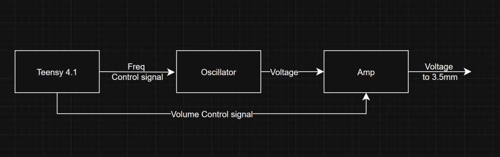
Okay so selecting the Microcontroller is easy: Raspberry pi’s are lame (I don’t want/need networking, display out, linux, ext), My arduino Uno uses usb-b and I’m pretty sure I don’t have a cable, so that leaves the Teensy.
On the oscillator side I could use:
- A 555 timer as a vco
- A Faster LC Oscillator that I can mix down to audio frequencies
- Op amp multivibrator
————
After quick review, oscillator #2 seems…hard, oscillator #3 could work but it seems like more parts than I wanna use… Which leaves us with oscillator #1!
To be honest I haven’t decided the amp but generally it could be one of two things:
1.) An i2c controlled IC from digikey such as https://www.analog.com/en/products/max98425a.html (if I want to waste money)
2.) A transistor setup that uses a control voltage from the micro-controller
Most likely it would be #2 but I’ll dig into that later
555 timer..time
Building a voltage controlled oscillator from a 555 timer is a pretty cookie cutter experience:
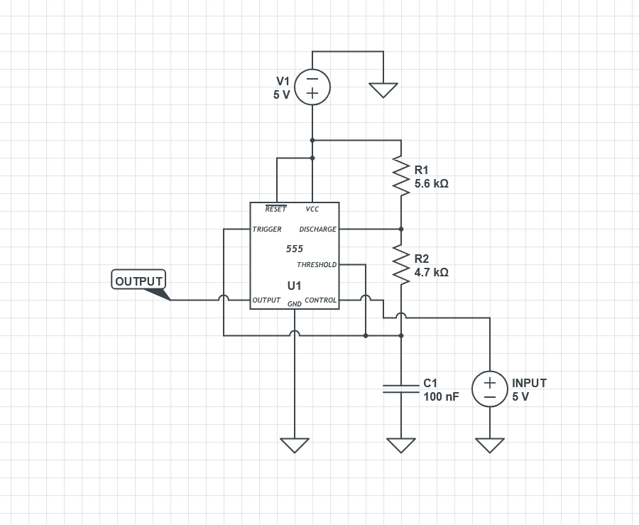
How ever it gets a little complicated when you try to choose your target frequency range.
In my case I’m aiming for 0.01-2000hz. In college I would do some math to figure this out but most of the equations are already solved in various places online. There’s also a systems management level to all of this, where maximizing your frequency span can create some odd artifacts etc.
So instead of being totally analytical I decided to be more visual:
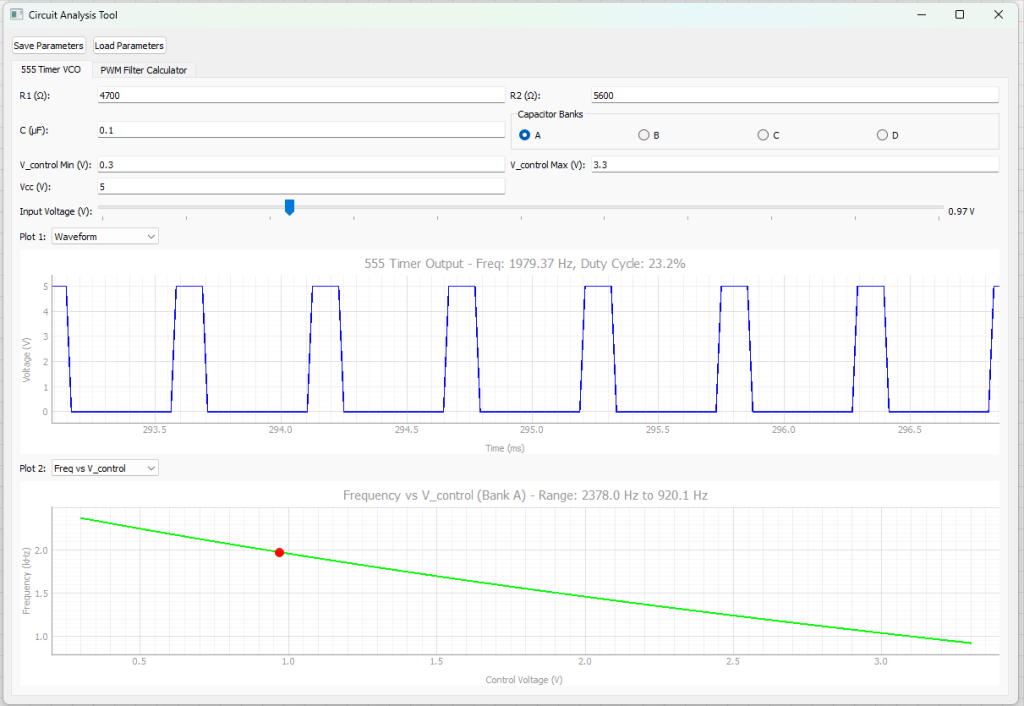
I made some AI slop where I can keep trying combinations until I get an output that I like. HOWEVER, I quickly realized the man problem of using a 555 timer: You really only get 5x of your lowest possible frequency. So in my case if my key frequency was 0.01hz, my highest frequency could only be around 0.05hz, if it wanted it to be 100hz, then my highest would be 500hz etc.
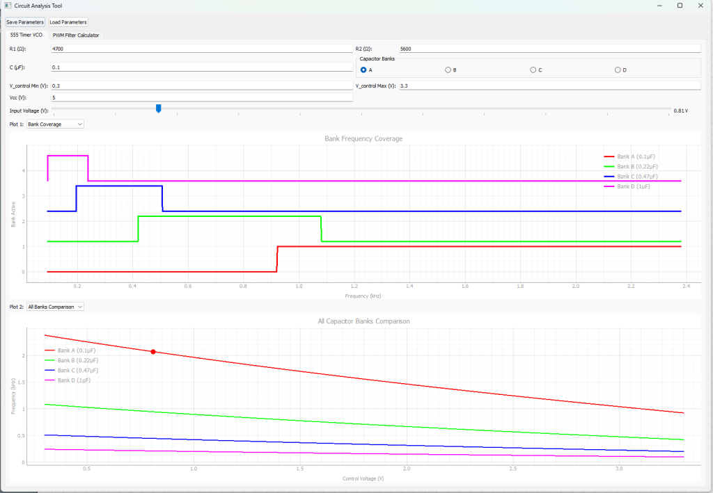
So how do we solve this? I could go back and figure out another oscillator type that has better control….OR I COULD THROW MORE 555 OSCILLATORS IN FOR COVERAGE!
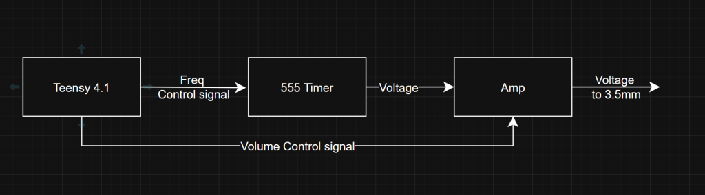
So then to update the block diagram:
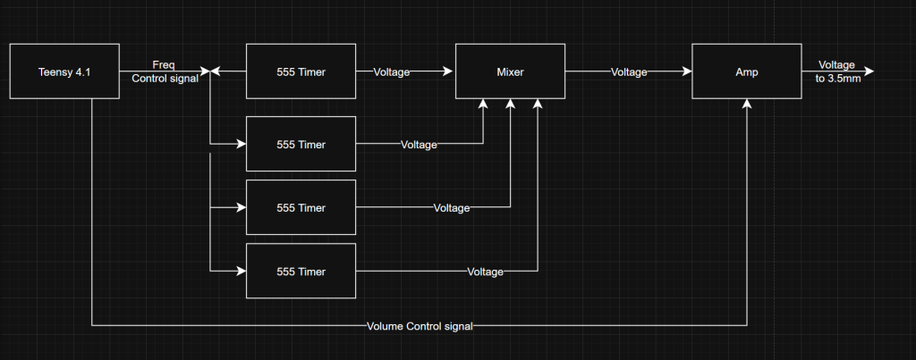
This is where I left off the oscillator bit. If I wanted to get a single tone out I could try using a single 555 timer with a mosfet to switch between a few capacitors (In the diagram above C1 is the major driver to your frequency range
Kinda doing dac stuff
So the teensy doesn’t have a dac. It it only has pwm, so how do I get an analog value out? Simple, just throw a capacitor (and resistor) in-front of the line and your square wave gets averaged based upon the capacitance of that capacitor (See this, again!). A.k.A you put a RC LowPass filter in-front of the pwm
Now there’s some issues with this approach:
- Your output will never be perfectly the level you want, a capacitor charges and discharges so if a square wave hits a capacitor you get some kind of voltage ripple
- The capacitor takes time to charge once you start hitting it with pwm, so if you choose capacitance that is too large it will take a long time to obtain your key voltage
- Your output voltage is limited from 0 to whatever the top level of your square is
————
So to summarize: my frequency range is limited by the control voltage into my 555 oscillator, which I can determine by a capacitance that I want to be big enough to stay stable when I choose a voltage but small enough so that when I choose a voltage it doesn’t take seconds to get the output to that voltage.
Again instead of doing math I made a tool!
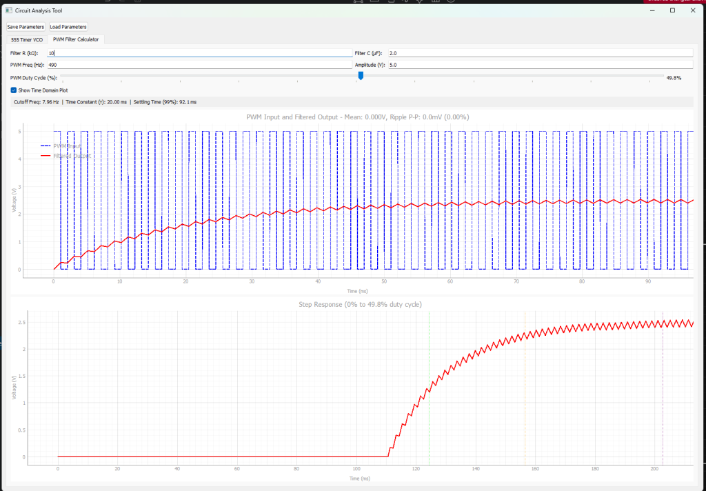
Now I can visualize what my control voltage will be based upon the resistor and capacitor
Main things I was trying to do is ensure that the output of my teensy can properly hit the range of the voltage needed for all frequencies of the 555 oscillator. In this case I can go from 0 volts to 3.3volts, and choosing a 2uf capacitor and a 10k ohm resistor seems to be the best trade off of voltage ripple at steady state, and step response.
Next steps
So I didn’t take any picture here but I have the high band 555 timer laid out on a breadboard and hooked up to the oscilloscope to see it working. The teensy pwm stuff is pretty simple in my opinion so I wasn’t rushing to get code written. My next steps for this are:
- Put the 555 timer on its own board
- Make the other 3, 555 timer boards
- Figure out how to make a mixer (and buy some knobs for the mixer)
- Figure out how to make a decent amp
- Hot glue everything together
- Sell on etsy (not really)
————
I threw the tools that I made (claude made) here: https://github.com/wfkolb/EEUtils/tree/main if you’re interested. Its mostly pyqt and a little numpy in the mix. I’ll try to keep that updated as I get more math in, I’ll probably throw a mixer and amp tab in to help me out there.